A Bc Circuit Diagram A+bb+c Circuit Diagram
Diagram of simple circuit Electrical circuit diagram image Solved (a) circuit a (b) circuit b (b) circuit b (c)
Generate Boolean Function Circuit
1. in the diagram, ba=a,bc=b,bf=c. using a,b,c F = a'bc + ab'c + abc' +abc A bc circuit diagram
Generate boolean function circuit
A+bb+c circuit diagramDigital logic design: full subtractor circuit Circuit simplification examplesFree circuit diagram pdf.
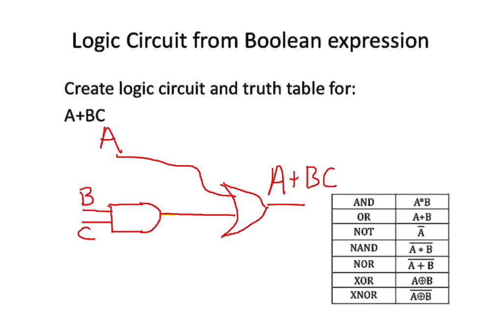
Solved draw circuits to realize the functions a) f= a + bcPin on electronics circuit A bc wiring diagram circuit diagramPower circuit of the proposed c³ bc.

Solved to implement f ab+bc+ a (b+bc), a, b, c are input. if
Simple circuit diagram for beginnersSolved given the circuit diagram below: a b c 5. (10 6. design a logic circuit to realize the following. (2)f(a,b,c) = abHow to draw a circuit diagram from a truth table.
Schematic diagram of bc.Ab draw bc circuits circuit realize logic functions cd truth solved table given following transcribed text show problem been has A bc wiring diagram circuit diagramSolved convert the circuit to an expression: ab+cab+bc abc.
Boolean expression logic circuit diagram
A+b+c circuit diagramC'+bc Ups schematic diagram pdfSolved bc:4.1 for the circuit shown below in fig. 1,.
Circuitlab circuit[diagram] original wire diagrams bc rich mockingbird Power supply circuit diagram pdf[solved] draw the circuit diagram for the following equation; (a+b+c.

Schematic circuit diagram — are.na
Ab+bc b+c circuit diagramSubtractor full circuit logic diagram digital two boolean derived functions simplified maps B. circuit diagram of device[diagram] electricity circuit electrical wiring diagrams.
.


